MACHINE MACHINING HEAD
Pic.8
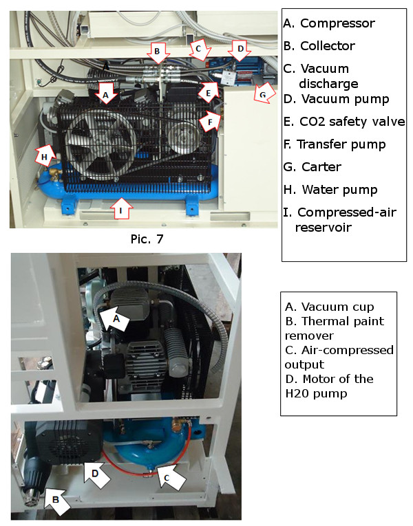
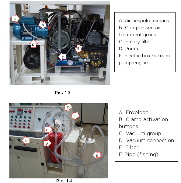
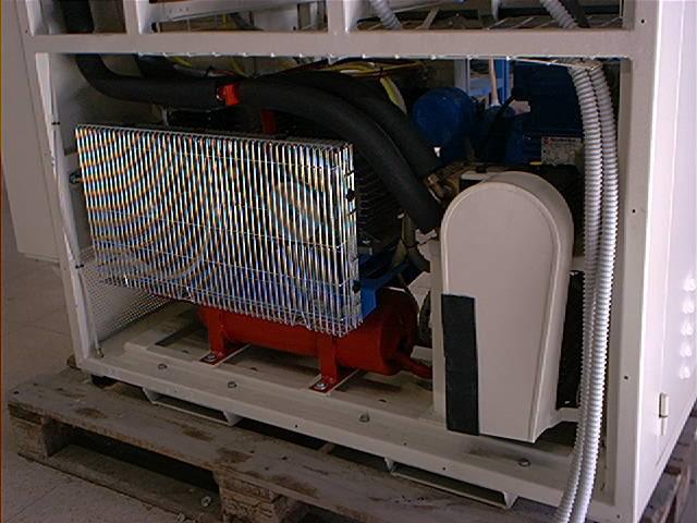
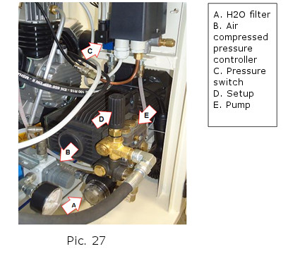
In the 7 and 8 pictures we can see the motor of the CO2 pump the vacuum pump for the filling and emptying the powder fire-extinguishers, the pump for the liquid CO2 transfer the water pump for the envelope hydrostatic test and for the hydraulic test of the fire hoses and air compressor.
COMPRESSOR (Pic. 7-A) :
18 bar air compressor for hoses dry pressurisation and all the tipical final auditing procedures cleanings
VACUUM PUMP (Pic. 7-D):
Pump provided with protection filters for the transferring of powders during the loading.
PISTON PUMP (Pic. 7-F):
Transfer pump for high-low press fire extinguisher medium fr thank to thank and from stocking thank to reservoir)
WATER PUMP (Pic. 7-H):
Using water to verify the fire extinguisher thank stability with a during 30 seconds water performance to a maximum pressure value hallmarked on the thank itself its also possible to effectuate a performance control on CO2 fire extinguishers where a 250 bar pressure is needed.
COOLING AIR BLOWER:
The air blower consent the air outlet avoiding the engine’s overheating.
CO2 AND GAS FIRE-EXTINGUISHERS REFILL
The operation requires to use a piston pump mountend on the heading machine of the device.
Pic.10
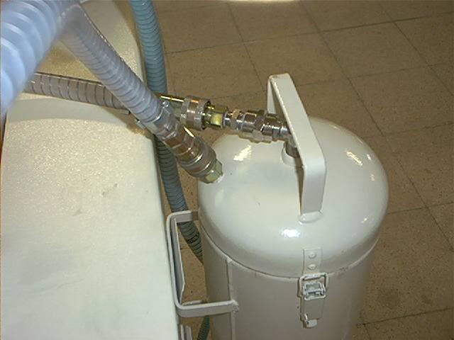
The pump does the transfer of the high-low pressure fire-extinguishers medium from a thank to another or from a storage thank to another. (Pic. 11)
Pic. 11
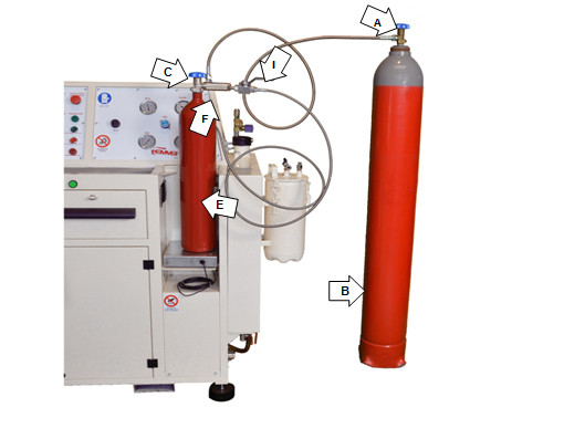
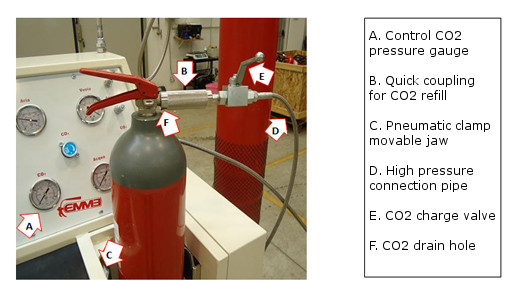
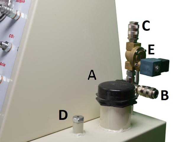
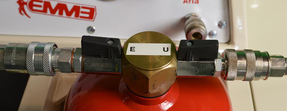
 The way of working for CO2 fire-extinguishers refill is represented in the picture and must be done according to the following steps:
- Take the fire-extinguisher to refill (Pic. 11-E)
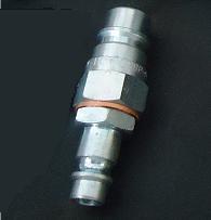
- Connect the fire-extinguisher ( Pic 11-E) to the quick coupling (Pic 11-F)
- Open the valve on the bottle (Pic. 11-A)
- Open the valve on the extinguisher (Pic. 11-C)
- Effectuate the weighing of the fire extinguisher.
- Reduce to zero (Pag. 50-Pic. 28) trough the apposite buttons
- Set the weight on the scale and proceed as follows: 1) Press the “Menu” button and the“F1” inscription will appear and after one second one value to set using the arrows (that’s the CO2 weight we want to insert in); 2) press the “Enter” button to confirm and the “F2” inscription will appear and after a second a value. 3) At this point press again the “Menu”button to exit from the programmation. Weight is now set.
- Open the load (Pic. 11-1)
- Connection is now effectuated.
- Wait for the CO2 transfer until 30% charge.
- Activate the pump trough the apposite button (pag 37 Pic 23-c)
- Wait it reaches the previous set weight.
The pump should turn off automatic. If not switch the pump off using the apposite button. (Pag. 37 Pic 23-E)
- Close the fire extinguisher valve. (Pic 11-C)
- Open the earth connection (Pic. 11-F)
- Wait the CO2 explosion relief from the apposite hole. (Pic. 12-F)
- Remove the earth connection (Pic 11-F).
- The cycle is now ended.
- After work close the valve on the bottle (Pic. 11-A) and vent the line opening the valve. (Pic. 11-1)
MAKE SURE THE PIPEWORK IS NOT UNDER PRESSURE
The pump with the automatic lock works when the scale is on. When the scale is off we can use an auxiliary scale but the charging (switching on or off the pump) must be done manually.
The CO2 pump must never work dry as one runs the risk to damage seriously the mechanism. In this case we must suspend the operation and make sure that the storage tank is full. If the thank is empty replace it with a full one and continue the transferring process.
Pic. 12
The operation entails the using of a vacuum pump aggregated to a machining head.
The vacuum pump provided with protection filters is used to the powder in loading and emptying.
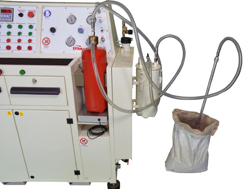
Pic.15
The filling operation takes place setting up the machine as depicted in the picture.
Using a particular equipment (Pic. 14-C) where the vacuum created from the vacuum pump for the machining head is exploited, is possible to transfer the
The emptying operation takes place using the filling equipment in reverse.
The previous operations for the connection are:
-
Take the envelope (Pic. 14-A) and place it in the installation chamber
-
Insert the suction group (Pic. 14-C) inside the envelope while taking care of the seal that must be taped to the envelope to avoid dust splashes toward the operator.
-
Weight the empty reservoir with the scale (pag.50 Pic. 28) and set to zero the value of the tare using the apposite buttons.
-
Block the fire extinguisher with the pneumatic clamp while actionizing the two buttons simultaneously (Pic. 14-B)
-
Connect the suction group to the sub-control panel (Pic. 14-D) with a tube provided with quick disconnect couplings.
-
Insert the tube with ring final part (fisher) containing the powder (Pic. 14-F)
-
- Start the refill procedure activating the pump with the button (Pag. 37-Pic 23C) aspirating the powder from the drum container. The weight of the powder inserted is monitorable with the scale (Pg 50- Pic 28) unblocking the fire-extinguisher from the pneumatic clamp with the button (Pag.50 – Fig. 28/2)
-
In event of suction capacity reduction open and close repeatedly the cleansing filter valve located on the top of the filter (Pic.14-E).
-
At work done switch off the vacuum pump pressing the button (Pag.37 –Pic.23E).
The emptying process happens switching the suction group with the powder fisher and keeping the connection unchanged with the operation panel's derivations.
Verify that the seal of the suction group is well located at the transfer moment so that is possible to avoid fire-extinguisher powder return flows outside the container.

Water testing
With a pump mounted on the machining head, trought the use of water is possible to verify the fire-extinguisher stability.
The water testing consist in a prevention measure likely to verify the stability of the reservoir or the fire-extinguisher bottle.
The test is carried out pressurizing the fire-extinguisher thank during 30 seconds to a maximum value stamped on the reservoir itself.
Pic.17 Pic.18
Pic.19
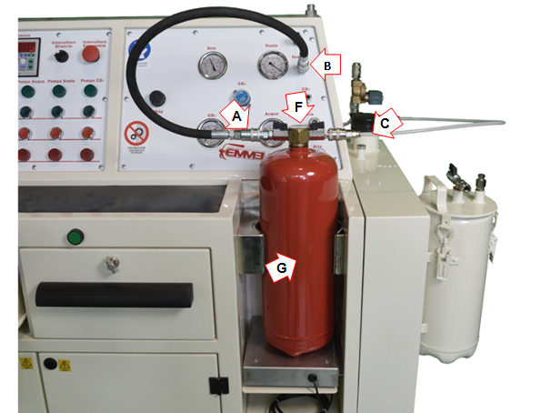
The procedure for placement to the realize the achieve the test is the following:
- Take the envelope (Pic. 19-G) and place it in the installation chamber.
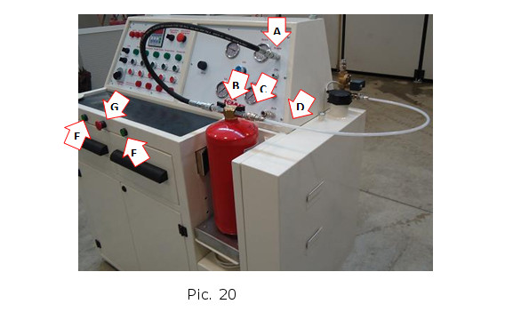
- Block the fire extinguisher with the pneumatic clamp while actionizing the two buttons simultaneously (Pic. 20-E/F)
- Screw the adjustable fitting (Pic 19-F) to the envelope to be tested with open valve and a fisher screwed in such a height to be nearly at the bottom of the reservoir.
- Connect the apposite tube with quick disconnect couplings (Pic 19-A) to the sub-control panel (Pic. 19. B).
- Connect the apposite tube with quick disconnect couplings to the water thank (Pic 19-C).
- Fill the water thank trough a tube connected to the coupling (Pic. 19-B) inserting the apposite in the dual nozzle adapter (Pic. 18) in the other coupling (Pic. 19-A) and actviting the pump trough the apposite button( Pag. 37 pic. 23-C) and wait until it flows water from the tube( Pic. 19-C ).
- Close the valve near to the tube (Pic. 19-C) and wait until pressure-boosting to the chosen value.
- Leave the envelope pressurised at the time imposed from the obligation.
- Verify that the envelope satisfies the imposed from the obligation requirements.
- End the test turning off the water pump with the button (Pag. 37 Pic. 23-E) and open the valve near the tube. (Pic 19-C).
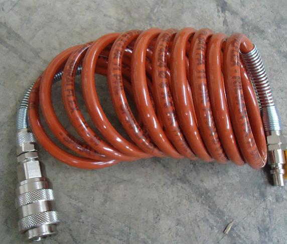
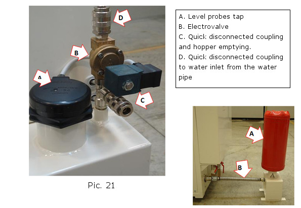
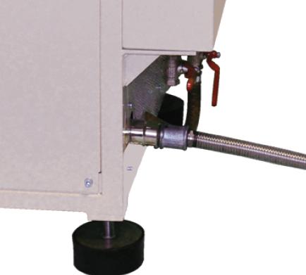
- To empty the water thank connect the junction (Pic 21-A) to the apposite dual nozzle adapter and to the “rilsan” air compression tubing section (Pic. 17). Connect the tubing section to the coupling (pag.39 Pic24F) and gradually open the tap. (Pag 39 Pic. 24-P)
- After work demount the tubes and the junction (Pic. 19-F)
- Before the envelope's filling use the industrial hot air generator located on the right side of the machine to dry the internal part( Pic.22) placing it as the picture depictes and switching the phone on pressing the button (pag.37 Pic. 23-C)
- Remember to work always with the water thank filled with water (Pag. 6 Pic. 2-B) Its automatic refill happens happens connecting the water from the water pipelines to the junction (Pic. 20 A-D) and activating the selector (Pag 37 Pic 23-G) In case of new filling before activating the selector wait until the thank is nearly empty.
Pic. 21 - Warning. During the drying operation either the metallic tube either the supporting are extremely hot. Operate exclusively with the apposite heat protection gloves to use for the dried reservoir transferring and wait until 15 minutes when the machine is off until the materials are cold.
Pic. 22
The drying process happens trough the hot water. (Pic. 22-B)
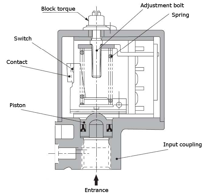
 WHAT IS AN ELECTROVALVE ?
An Electrovalve is merely a tap that allows the fluid flows through the gap identified by the valve itself, and then branching in the conduits (in the broad sense) that are located downstream being downstream the section where the pressure is higher.
The “electro” in the name designated that the actuator of the mechanical activating of the valve, traditionally a human operator or the mechanical predisposed postponement is replaced by an electronically controlled, usually a solenoid.
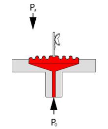
Functioning

Over an open valve
Under an open valve
A.Entrance
B. Diaphragm
C. Compression chamber
D. Decompression Conduit
E.Solenoid
F. Exit
CATEGORIES
The easiest Electrovalve consist in a mechanical opening and closing device that is actuated by a solenoid. The solenoid, when current runs trough it attracts a magnetic core inside an internal channel and thus the mechanical displacement of the device’s tigh-element and the opening and closure of the Electrovalve (all or nothing). Such simple electrovalves can be actuated by continuous or alternating current.
The electrovalves are classified depending on several criterias including:
- the internal flue lines disposition (positions and ports)
- the firing typology (DC, AC)
- the balance conditions (monostable, bistable)
The port number indication (connection nozzles) and positions (outlets final condition) is obliged from the DIN ISO 1219 norms.
A monostable electrovalves has a balance position that fits the rest positon meaning non powered. When powered it turns on; when the power is absent goes back to the rest position. A bistable electrovalve is provided with two solenoids, each one with its proper power. The balance position is the last to reach. To change the position it is required to power briefly the other position solenoid. If both the powers are activated or none of them the condition of the valve does not change.
In addiction to the solenoid electrovalves there are other kinds of driven valves whose action can be progressive. The electric actuator can be, in this event, a motor that moves the tigh-element trough mechanical quickdraw, physically checked, trough position-indicating functions or automatic braking control driven. Such controls can assure the achievement of the required position or in more complexed systems continually adjusts the valve opening and closure. Depending on the required effects downstream detected from closed chain control elements.
UTILIZATION
An electrovalve particular case are those used in the electronical input engine where a rectifier open and closes for very short period of time (milliseconds) the oil flow in the engine cylinders, depending on the utilisation requirements.
OPERATION PANEL
The control is located on the back side of the machine. The accessibility to the commands is excellent and allows the operator to act saving energy and time.
The control panel is divided in two sectors:
- Electric drives panel
- Operation panel and derivation of the system
ELECRIC DRIVES PANEL
The electric drives panel is a machine integral part and is installed on the front part of the machine.
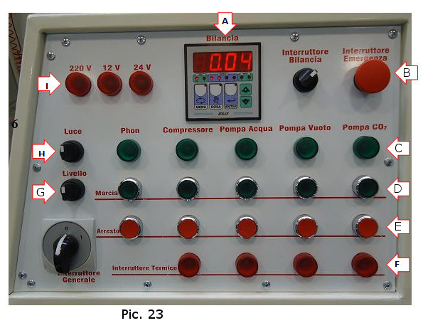
The electric drives panel consists in:
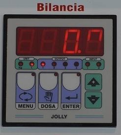
1. Electronic scale display (Pic. 23-A)
2. Emergency button (Pic. 23-B)
3. Control lamps of active group (Pic. 23-C)
4. Activation buttons (Pic. 23-D)
5. Stop buttons (Pic. 23-E)
6. Thermic intervened lamps (Pic. 23-F)
7. Water refill button (Pic. 23-G)
8. Light power selector (Pic 23-H)
- Selector on mode 0: the device is deactivated from any electric power source
- Selector on mode 1: the machine is powered by the batteries
- Selector on mode 2: the machine is powered by the distribution system.
9. Voltage board indicators (Pic. 23-I)
OPERATION PANEL AND DERIVATION SYSTEMS
The operation panel and derivation systems is mounted on the operator’s right.
The position is really close to the enevelope’s fire extinguisher’s locking compartment to consent the connection to the various system derivation: water system, vacuum sunction system, CO2 pumping system and air compression system.
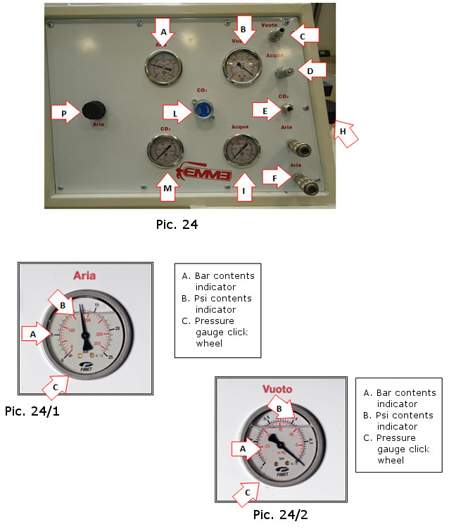
The operation panel and derivation system is composed by:
-
Air compression system pressure gauge. ( Pic 24-A)
-
Vacuum system pressure gauge (Pic 24-B)
-
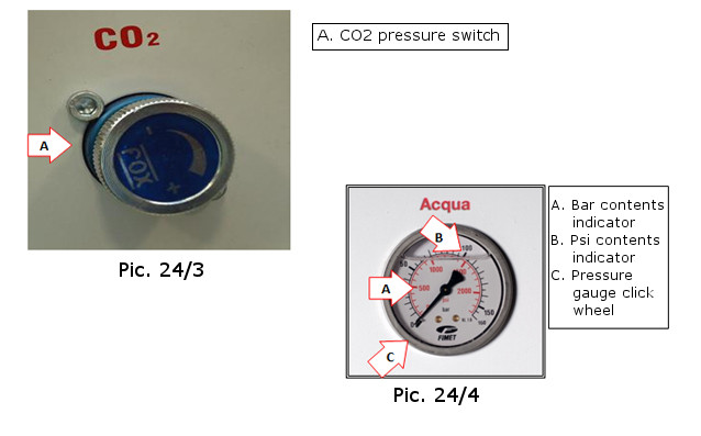
CO2 pressure switch (Pic 24-C)
-
Water system derivation (Pic. 24-D)
-
CO2 pumping system derivation (Pic 24-E)
-
Air compression system derivation (Pic 24- F)
-
Water system pressure gauge (Pic 24- I)
-
Pressure gauge to control the CO2 system pressure. (Pic. 24-M)
-
Button for activating the air compressed circuit (Pic. 24-P).
WHAT IS PRESSURE GAUGE ?
A pressure gauge is a mechanical instrument designed to measure fluid’s pressure. The correct meaning of the lemma refers to the instruments dedicated to the measurement pressure greater than the atmospheric; for lower values than the atmospheric pressure the correct term is vacuometer or vacuum gauge (to measure the vacuum).
Originally the word pressure gauge was only referred to hydrostatic tools with column liquid now named U pressure gauges has been extended to embrace quadrant and digital tools.
There are various kinds of pressure gauges suitable for various works. Most of them to tell the truth measures a relative pressure meaning the differential from the atmospheric pressure at the measuring point and the pressure of the environment that you want to measure. Those include the U pressure gauge, the diaphragm pressure gauge. Bourdon.
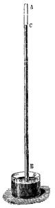
U pressure gauge.
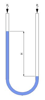
U pressure gauge.
They are composed from a tube (usually transparent) U curved and filled with a fluid of known density. One of the edges is leaved open to the atmosphere the other is directly connected with measurement environment. The liquid contained in the tube will flow upwards trough one of the two U limbs so much as the weight difference between the two columns of liquid exactly balances the pression or depression) present in the measurement environment. For the water vessels is often used the ɣm = 13000 N/m mercury. See the 1 picture for the scheme. If the valued are expressed in coherent units we will have:
| ρ . g . H | = |P0-Pa |
where:
Being extremely simple such pressure gauge is not susceptible to failures. Its resolution is not very high because of the unavoidable meniscus phenomenon.
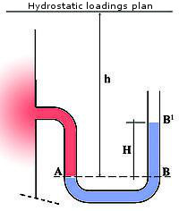
U pressure gauge
On the horizontal plan that goes trough the meniscus A the pressure will be equal in the two limbs:
P0 = Pa = ɣm . H
When the connected container is full of liquid we will have:
h = P0 / ɣ = Hɣm / ɣ
where:
-
h is the sinking of the A meniscus under the hydrostatic loadings plan of the liquid in the container
-
ɣ is the specific weight referred to the liquid in the container
-
ɣ is the specific weight referred to the liquid in the pressure gauge, m stands for mercury
Make sure that in case that the pressure in A its negative the B meniscus in the open branch should lie at a lower quote than A itself.
Bourdon Pressure Gauges
Bourdon spring
They’re composed from a tube usually from elliptical wich assis is located following a circle ( but can be wrapped even for more than 360° and take the form of a spiral.
Known as Bourdon tube. It was noticed that a tube of this form tends to augment its proper radius of curvature when the tube internal pressure augments; the radius measure is the pressure measure. Practically the tube is connected to a limb with a fixed point linked to the Measuration environment, the other limb is connected to a float arm that amplifies its moving and transforms it into a circular movement of an index on a graduated scale. See picture 2. The bourdon manometers are the most of the pressure measuration tools used today.
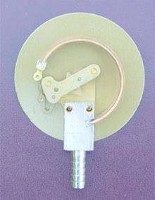
Diaphragm pressure gauge:
Diaphragm pressure gauge:
Diaphragm seal so called diaphragm type because the deformable element is a diaphragm usually corrugated to augment the flexibility. The diaphragm separate the measuring environment from outside, and will swell if the pressure to be measured is higher than the atmospheric or vice versa. The float board nearly similar to the Bourdon pressure gauges expands this swelling and transmit it to an index as the Bourdon pressure gauges. There are several kinds or diaphragm pressre gauges generally used as differential manometer( see below).
Piezoelectric pressure gauges
They exploit the properties of some material known as piezoelectric to generate electric power on the voltage difference when to the material is exerted a pressure.
Vacuum gauges
Torricelli barometer
As we have seen, the described above pressure gauges measure a difference compared with the atmospheric pressure at the measuring point, meaning a relative pressure. Those tools can be used even as vacuometers or vacuum gauges improper word but really used they can indicate a negative pressure ( more precisely a negative pression difference compared to the atmospheric pressure. However in some cases is needed to measure the absolute precision very used in the technic application and phisics. For our environmental limitations cannot be used as a measure’s practical descendance a perfect vacuum, this problem can be solved creating artificially the perfect vacuum conditions.
The first application of this principle is due to Evangelista Torricelli who measured the atmospheric pressure ensuring that a vacuum chamber was created (the A-C zone of the side picture). To thell the truth in the chamber there was no perfect vacuum but ultra-vacuum because the mercury inside the tube having a low vaporishing pressure vaporized lightly- the mistake was negligible.
Today the tool most used to measurate with preciscion the absolue precision is the Barton cell aneroid barometer revolution.
The Barton cell was born to be a differential pressure gauge; taking the perfect vacuum as reference like in the Torricelli experiment becomes a absolute pressure meter. The vacuometers are divided in 3 groups: low vacuum and high vacuum and ultra- vacuum combining these groups in a single graded scale we can measure pressures from 10mbar to 10e-11 mBar. Liquid pressure gauges are constructively different from the gas ones.
WHAT IS A PRESSURE SWITCH?
The pressure switch is a two state device (open and close form a button) used for the simple management of a device that produce a set pressure value of a fluid.
Differently from the pressure gauge cannot effectuate any measuration: the device in fact has a trigger point level usually at a distance from the deactivation point level with an appropriate hysteresis; suitable for the limitation of of the commutation’s side effects around the threshold value.
TYPES OF PRESSURE SWITCH
The most common models are electro-mechanics where the mechanic element immersed in the fluid triggers a genuine breaker trough a float board.
The basic flaw of this technology stands in the relative complexity of the mechanical groupset and the need of decent mechanical seal and of the moving parts electrical contact’s intrinsic unreliability. For the most critical applications are available simplified mechanics model and solid form position sensors provided such as semiconductors Hall-effect or photocells (mostly frequently composed by the Led and phototransistor duo) or made without any moving par, trough linear pressure transmitters connected to a trigger circuit.
SETUP
The pressure switch can be calibrated trought two setup:
- Driving pressure in the mechanic models the action threshold can be modified adjusting the lever arm length or most commonly of the counter-spring trough a adjustment cap.
- Coupling pressure, in the mechanic models can be setup trought a second setup to deactivate the pressure switch trip, setting up spring preload of a second spring.
SECURITY AND EMERGENCY
The machine is provided with a switch mushroom on the electric operation board (pag 37-pic- 23-B) that ensures to the operator a quick time intervention.
To operate with maximum safety the machining head is totally closed in carpentry carved compartment safeguarded by fixes barrier guards, an interlocked guards.
The circuits are provided with control and quick jettisoning groups, in event of higher than the normal use of the machine working pressures.
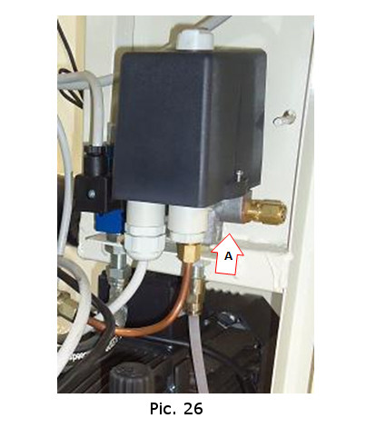
Pic.25
The compressed air system has a quick jettisoning valve located on the reservoir that assures the danger of busting safety. (Pag. 48 Pic. 26-A)
The other systems( vacuum system, water system, CO2 pumping system) are realized so that they can be individually controlled from a pressure switch that when a preselected pressure limit is reached stops the related pumps activation.
 ZOOM- FINE DETAILS
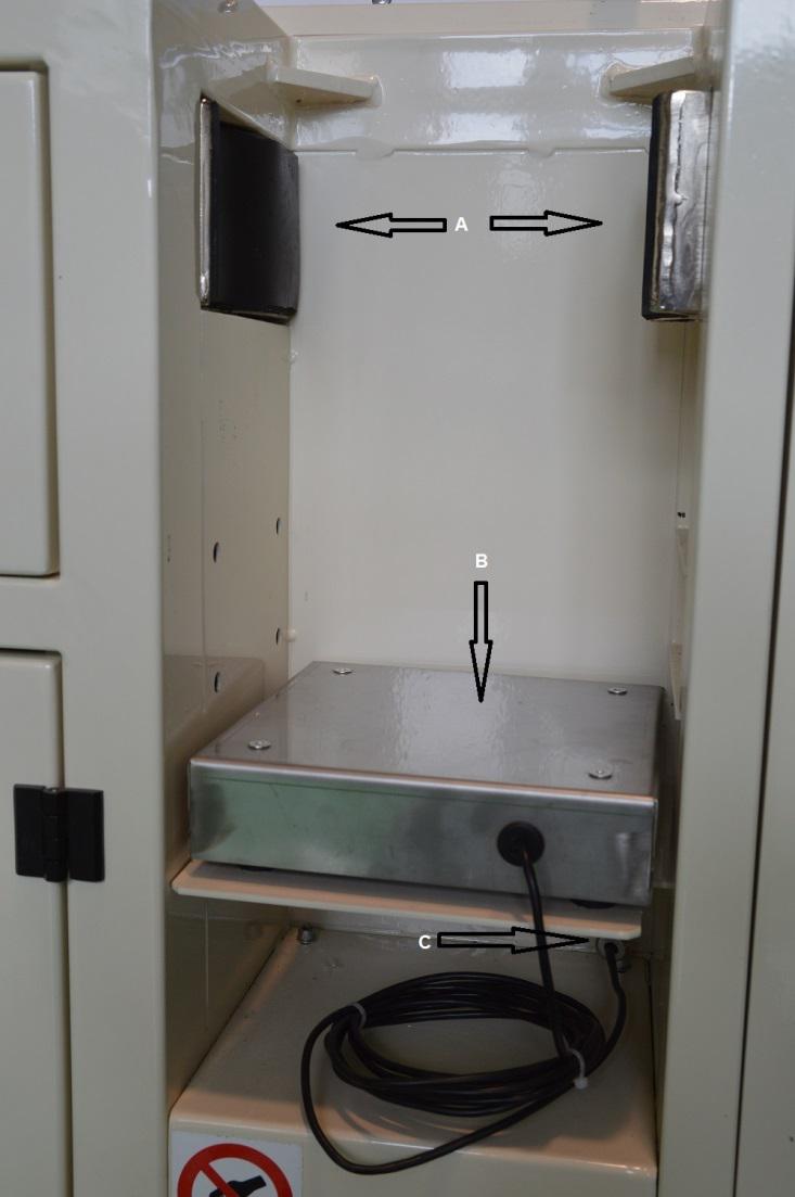
ELECTRONIC SCALE PNEUMATIC CLAMP PROVIDED
Pic.28
Pic.28/1

Pic.28/2
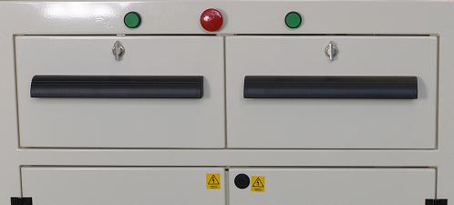
Electronic scale (pic. 28-B) display provided (pag. 28/1) around 30 kg, for all the portable fire- extinguishers.
The pneumatic clamp (Pic. 28-A) has a fixed part (the right one) and a movable part (the left one). To drive the clamp there are two green buttons under the operation panel (Pic. 28/2), for physical safety the are to be switched simultaneously and to reopen the clamp we must press the red central button.
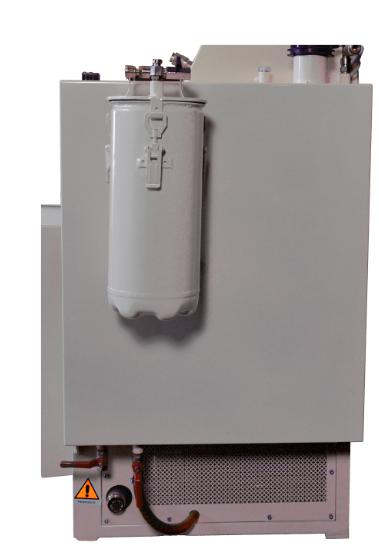
INOX THANK FOR WATER TESTING
Pic.29
Pic.29/1
Inox water recovery thank capacity 80 litres (Pic 29) electro valve provided (Pic. 29/1-E) that opens or closes depending on the internal probes command (Pic. 29/1-A) the two taps are intended, one to channel water to the external tap, the other to the emptying of the thank. (Pic. 29/1-C, B). In addition we can see the breater intended to release the pressure. (Pic. 29/1-D).
Containers (that can be slewed) for powder replacement, filter provided.
Pic.30
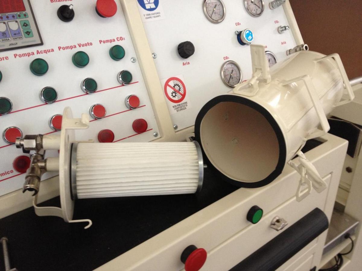
Pic.31
FIRE HOSE WINDER

Pic.32
After the dry or water performance control the hose can be easily retracted thanks to this winder
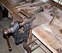
Warning: Instead of the hose is possible to install a bench vise.
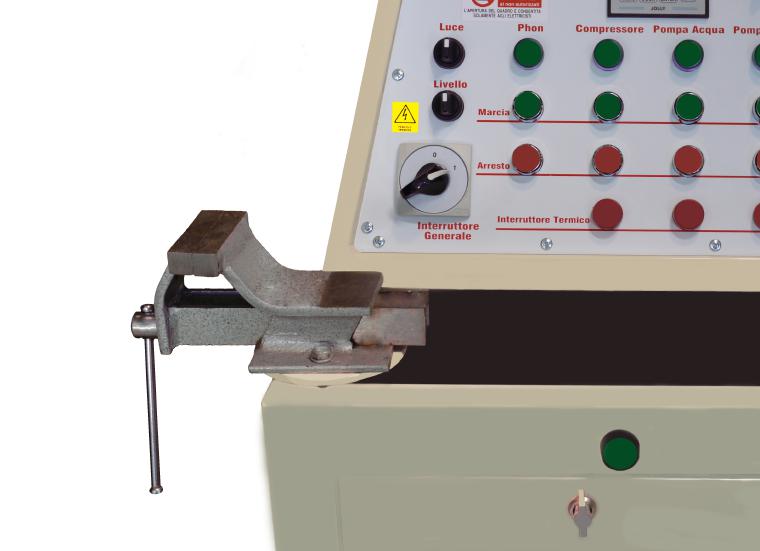
Pic.33
What is a clamp?
The clamp is a single screw on tool mechanic utensil suitable to clamp and withhold the workpieces, usually for adjustment, thread, sawdust, welding, installation of other components, bonding included. The most common models are in fused steel or in cast iron but there are wooden models too. The clamping force can be obtained with a hand-manoeuvrable screw pressing the sliding handlebar grip.
The screw moves a movable jaw that tightens the part toward a symmetric fixed jaw. The jaws are often of metal sheet coated, so call “nibblers” usually in copper, lead, light alloy, in order to avoid ruining the tighten piece.

A) parallel bench vibes
1 handler
2 maneuvering screw head
3 reported jax
4 fixed jaw
5 screw fastening clamp
B) machine clamp
C) little clamp
At the work bench the clamp labours can be done by hands using a file, sandpaper, a plane, male, chain, hacksaw, drill, reamer, savoir and so on; worked by machine trough the milling machine or the boring machine.
CLAMP TYPES
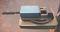
Machine clamp, we can see the V carving.
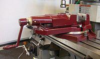
Revolving precision vise intended for machine we can see the setting cirlces and the oiling points.
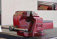
Parallel bench vise, in the picture we can see the lead scold's bridle
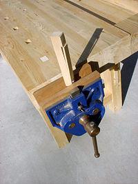
Bench vise intended for wood.
A type of articulated vise
The clamp is an essential part in every work bench. Its vertical position affects the correctness of the workpieces and the fatigue employed from the operator to create them. As an indication for an averaged size person the work bench is about 80 cm in height from the pavement and vise is installed in such a way that leaning your elbow on the top of the jaws and keeping the forearm in vertical we are able to lean the chin on the hand as a fist.
The clamps dimension is indicated with two numbers the first precise the jaws length, the second the extent of clamp fully opened for example 150x 220mm. The vise’s dimensional standards are unified form the UNI5271 AND 5272 norms while the thread of the manoeuvre thread is in general of Acme type.
Is produced in various types that can be divided in two large categories:
-
wooden intended
-
metal intended
The former are very large and integrated in the carpenter work bench narrow side to not exceed in height; made out from wood or sometimes in wood with metal fittings, the jaws are almost always wooden or plastic, rarely in metal and in this case have wooden scold’s bridle to avoid ruining the tighten pieces.
The latter are attached to the table of the bench or of the machine trough screws or clamps or suction cups when they do not have to support greater stresses, the little ones do not envisage attachment and maintain the position only for their weight; some can spin and tilt and the most precise are provided with gauges and noni.
To consent the piece insertment some allows the rapid dismount of the front jaws trough the adjustment nut.
Among the various model are included:
-
bench or table parallels also called prismatic pair intended because the shape of the dovetail ways slides; the most popular are made out from cast iron with reported jaws in hardened and knurled jaws that open remaining parallel to each other. There are steel vises that are less prone to breakage, in the case the type of tooling involves repeated hammering on the workpiece.
-
parallele machine suitable they have a trim frame profile and sometimes the jaws are V carved to consent the price axiality , they are often swivelling; can be used with milling drills and milling machines.
-
articulated whose jaws can open forming an angle instead of being parallel, being the mobile wall of the vise hinged on the fixed. The gripping of the workpiece is less firm then in the parallel vise as a result of the jaws non-parallelism; the typical blacksmith vise.
-
“gooseneck” type also called misaligned like the parallels but with curved jaws gooseneck type similar to consent the closure of shafts and spindlers
-
sine vises used when a high angular precision is needed, use sine bars or stricker blocks for tringle of the frames
-
shank clamp, they have a long clamp that leans on the floor to consent the hammer riveting of the thigten pieces, are mostly used in the forge.
-
tube intended, they have jaws V carved with vertical fastening, bolted to the bench.
-
small handle clamps, screw plug driven by the thumbscrew handle; are often use in the high mechanical precision field, watchmaking, electronics, and hobbies.
EMPLOYMENT
To work with the vise with comfort we should place on the side, around 45° ° from the screw axis and a half-meter from the bench assume a posture slightly tilted with the left foot forward and the right foot backward and the left knee slightly flexed so that be able to swing with the body taking as one’s base the right leg during the adjustments labours.
In the event of precision labours the posture may be different because we should come very close to the piece.
In order to avoid the deformation of the piece it is convenient to tighten it between the scold’s bridle so that only a small part protrudes, preferring the jaw’s central zone if its dimensions were inferior than the mouth opening. That’s because the vise’s edge wear can take place in a more or less reinforced jaw’s obliquity during the tightening, more likely on the prismatic slides models.
The utilisation of extension cables (pipes, keys) when we adjust the handle adjustment rod because the rising of the lever arm and the consequent force exerted can easily cause the vise breakage.
The use of the scold's bridles assure a better grip and more uniform and soft at the same time and lessen the risk of scratchings and deformation of the piece.
Usually, for adjustment’s labour with the file are employed steel scold's bridles, for the tightening of threaded parts, it is convenient to use lead.
In the carpentry plastic or wooden scold's bridles are preferred.
Maintanance
The vises require low-maintenance. At work done it is convenient to clean them with compressed air and make sure that there are not scraps of paring on the screw.
Every now and then they need to be lubricated with oil or grease in particular it is recommendable to oil the slides or the sliding parts and grease the screw. The highquality models have oiling points with ball check valves.
WATER TEST EJECTOR
Pic.34
In the top of the ejector are located the inlet and outlet connection cables
Pic.35
Under the operation panel there are two very large drawers used for the continence of the maintenance tools.
Hot air generator
Pic. 36
INSIDE OF THE ELECTRIC CONTROL PANEL

The K group are the COMMAND COILS, the F group are the motor’s THERMAL PROTECTORS
K3 -> COMPRESSOR command coil F3 -> COMPRESSOR thermal protector
K4 -> WATER PUMP command coil F4 -> WATER PUMP thermal protector
K5 -> VACUUM PUMP command coil F5 -> VACUUM PUMP thermal protector
K2 -> THERMAL DIFFUSER F2 -> THERMO DIFFUSER thermal protector.
K6 -> CO2 PUMP command coil
<<< Previous Page